What is the common link between papers talking about 'Flow Over a Mars Return Aerobrake', 'Parker Instability in Galactic Gas Disks and the Solar Atmosphere', 'Astrophysical Flows', 'Solidification with Magnetic Fields and Reduced Gravity' and 'Modelling of Hall-Héroult Cells'?
As if the challenge of solving the Navier-Stokes at high Reynolds number, dealing with turbulence, free surface flows, etc. was not enough, solving MHD driven flows also involves the solution of Maxwell's equations. Furthermore, in most cases, the Navier-Stokes and the Maxwell's equations are tightly coupled, through making the problem even more non-linear in nature.
Despite the complexity of the physics involved, which directly translate into greater difficulty in producing engineering designs, industrial metallurgy applications based on MHD are more and more common these days. They include: electromagnetic pumping, electromagnetic stirring, electromagnetic valves, electromagnetic casting and even electromagnetic propulsion. As initial reference on the subject, 'MagnetoHydroDynamics in Process Metallurgy' from the Minerals, Metals & Materials Society (TMS) is suggested.
Some academic institutions have developed extensive expertise in this very specialized field of CFD applications. In Europe, for example, we can mention MADYLAM in France, the Department of Engineering at Cambridge University in the UK, the Department of Mathematics at École Polytechnique Fédérale de Lausanne in Switzerland and also the Institute of Physics at Riga University, Latvia. In the United States, the Department of Materials Science at California's Berkeley University. the Department of Aerospace Engineering at Pennsylvania University and MIT's Department of Materials Engineering all work in this field. All of them have developed special purpose in-house CFD codes to study MHD flows.
Commercial general purpose CFD codes are usually not able to solve MHD flows. It is, however, possible to use, in combination, a commercial code to solve Maxwell's equations and a code solving Navier-Stokes equations to do so. One possible combination the author is familiar with is ANSYS and FIDAP finite element codes.
As an example of an MHD flow problem, let's describe the modelling of the MHD flow in Hall-Héroult aluminium reduction cell. The Hall-Héroult process involves the passage of a big DC current (up to 300,000 A) in a liquid electrolyte to reduce the aluminium oxide dissolved in it into aluminium. The liquid metallic aluminium accumulates as a second liquid phase in the cell.

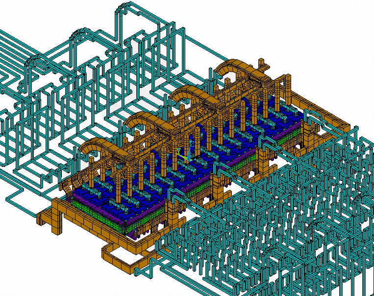
Figure 1 : Mesh of an aluminum reduction cell MHD model
The passage of this DC current in conductors connecting individual electrolytic cells, as well as in the cells themselves. generates an intense magnetic field. The computation of this magnetic field with a standard finite element method is, on its own, a challenge, since we have to deal with local distributed current sources in the liquid domain of interest, far field current sources from the external conductor network of the full potline with, in between, a multiply connected ferro-magnetic shielding structure called the potshell responsible for the structural integrity of the cell.

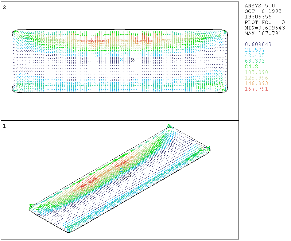
Figure 2 : Lorentz force at the middle of the metal pad computed by the ANSYS software
The current density in the liquid zone cannot be decoupled from the MHD flow solution, since we have to deal with two liquid phases separated by a free interface; because one liquid is a poor electrical conductor (the electrolyte) and the other is a very good electrical conductor (the liquid metallic aluminium), the position of that free interface strongly influences the current density distribution in the liquid domain.
The coupling effect is best explained by describing the global system: the passage of the DC current in the liquid zone as well as in the external conductor network generates a magnetic field. It also generates a current density field in that same liquid zone which, combined with the magnetic field, produces the Lorentz force responsible for MHD flow. The coupling effect comes from the fact that, to compute the Lorentz force required to feed to the Navier-Stokes solver, the position of the free interface is needed as an input, while this free interface position is part of the Navier-Stokes solution.
Another challenge comes from the fact that only the curl part of the Lorentz force field will dictate the flow pattern, while it represents less than 10% of the total field intensity. If you consider that the magnetic field is computed from the gradient of a scalar potential, the current density field is obtained from the gradient of the voltage and the Lorentz force is the vector product of these two fields, one must verify that the solution of the curl part of the Lorentz force field is not mesh sensitive before feeding it to a Navier-Stokes solver.

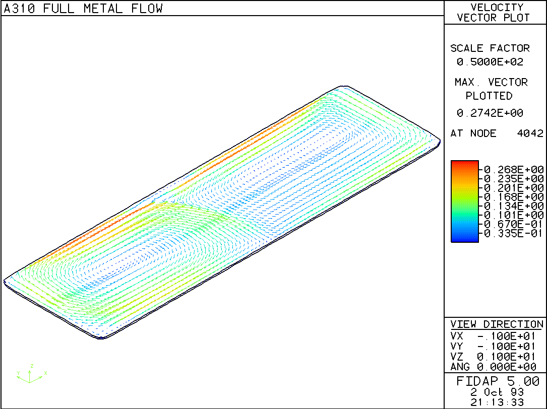
Figure 2 : Velocity field at the middle of the metal pad computed by the FIDAP software
There is also a specific requirement on the CFD solver itself, the selected code must be able to handle the solution to a two immiscible liquids flow problem which includes the solution of the position of the free internal interface. Only a few general purpose CFD codes handle this type of problem well.
If one considers that the dynamic coupling between
the Lorentz force field and the velocity field is responsible
for MHD driven process instability in aluminium reduction cells,
one can understand why it is such a challenge to solve it numerically,
while still accurately representing the key physics involved!