
CATHODE SHELL STRESS MODELLING
M. Dupuis, G.V. Asadi, C.M. Read, A.M. Kobos Alcan International Limited Arvida Research and Development Centre 1955 Mellon Blvd., Jonquičre, Québec, Canada G7S 4K8. Telephone (418)699-3237, Fax (418)699-6378 A. Jakubowski JJ Desinex Inc. Suite 206, 2350 Herron Road, Dorval, Québec, Canada, H9S 1C5
|
Abstract The present work describes a study of the structural behavior of the cathode shell of a 65 kA Hall-Héroult cell. The work, which was carried out at the Alcan International, Arvida Research and Development Centre, used the commercially available Finite Element code ANSYS (1). In particular, the response of the cathode shell, including both the shell deformation and the stress distribution in the shell, to the forces generated during cell operation was investigated. Mathematical modelling of the shell deformation and stress distribution made it possible to identify relatively weak sections of the shell. Further, an in depth analysis of the progressive shell deformation over an extended period of operation lead to an understanding of the failure modes of the shell. It demonstrated that based on such analyses it is possible to redesign the cathode shell and subsequently extend cathode life. Advanced computer graphics and animation techniques were found to be essential tools throughout these studies. Consequently, an animation of the shell deformation and stress development in the cathode shell is presented. Introduction The average cathode lining life of a Hall-Héroult cell may vary typically from 1500 to 3500 days. For a particular Hall-Héroult cell technology, the average cathode life is determined by various design parameters (e.g., cathode shell strength, collector bar configuration) and operational factors (e.g., pre-heat practices, cell internal heat). Further, it is frequently observed that the ultimate failure of a cathode is due to an undesirable interaction between the cathode shell structure and the physical and chemical phenomena which occur within the cathode lining during cell operation. Economics decree that it is always desirable to design and fabricate a cathode lining and cathode shell which will survive over a long period of operation. However, in today's industrial climate, an extension of cathode lining life is favorable from an environmental as well as from an |
economical point of view; an increase in cathode lining life leading directly to a reduction in the annual rate of generation of "Spent Pot-Lining". Consequently, the aluminum industry has large incentives to extend cathode lining lives. The mechanical design of the cathode shell of a Hall-Héroult cell is one of the most important factors which influence cathode lining life. A well-designed shell is one which is able to withstand the internal pressures which build up within the cathode lining during cell pre-heat, start-up and subsequent cell operation. In fact, the cathode shell deformations caused by these internal forces should be limited to the elastic rather than the plastic range, i.e. the cathode shell does not yield and exhibit permanent deformation. A better understanding of the behavior of the cathode shell structure during all phases of cell life and operation is essential if we are to extend average cathode lining lives through improved cathode shell design. Traditionally, the classical methods of mechanical engineering analysis, combined with the skills of the mechanical engineer, were used to deliver new cathode shell designs and to optimize existing designs. In recent years however, numerical analysis of engineering problems, allied with advanced computer hardware and software capabilities, has made it possible for engineers to study the behavior of cathode shell structures more closely, more accurately and more successfully. Finite Element Approach The application of Finite Element numerical techniques to the engineering analysis of complex structures has created opportunities in the realm of design and optimization of the Hall-Héroult cell cathode shell. Further, the development of commercially available software programs has increased the availability and applicability of those powerful analytical techniques. At the Arvida Research and Development Centre of Alcan International Limited, the finite element code ANSYS (1) was used to analyze the structural behavior of a 65 kA Hall-Héroult cell cathode shell throughout its life. A finite element mathematical model of a quarter of the symmetric |
|
cathode shell design was developed. The model geometry and corresponding sub-division to definite elements' is presented in Figure 1. This model, initially coupled with a simple linear-elastic analysis, was used to examine the structural response of the cathode shell to the internal pressure developed in the cathode lining during operation. The linear-elastic model was used to calculate the deformation of the cathode shell and the distribution of stresses generated within each structural component of the cathode shell. An examination of the stresses predicted by the linear-elastic model revealed a number of structurally weak components in the cathode shell. It was observed that at certain points in the cathode shell a plastic hinge had developed, thus implying permanent plastic deformation of the cathode shell at these locations. A comparison of these model predicted locations with the observed points of weakness on old cathode shells (i.e., heavy shell distortion and fractured welded joints) showed the model predictions to be in good agreement with reality. Based on the favorable results from the linear-elastic analysis, to calculate the precise cathode shell deformation and the corresponding stress distribution, a fully plastic analysis of the 65 kA cell cathode shell over a given period of cell operation was undertaken. The shell deformations predicted by the plastic model were shown to be in good agreement with those measured in the field. Further, these results confirmed that it was possible to accurately predict the behavior of the cathode shell over long periods of cell operation, even over the entire cathode life. In addition to the use of the structural analysis capabilities offered by finite element techniques and commercially available software codes, the power of present day computer hardware and state-of-the-art visualization techniques were used to assure an efficient and thorough analysis of the model results. For the 65 kA cell investigated in this work, a computer-generated animation of the cathode shell deflections and the distribution of three-dimensional stresses in the shell is presented. It can be seen that an analysis of the mathematical modelling results over the entire cathode life would be virtually impossible without these powerful tools. Further, the ability to follow the build-up of stresses within the cathode shell over a period of time gives the mechanical engineer a thorough understanding of the behavior of a particular cathode shell design, such that modification and optimization of that design are possible. Optimization of Cathode Shell Structure An ideal cathode shell structure may be considered to be one in which there is a uniform distribution of stress along all components, i.e., no specific component is |
over-stressed or over-designed. The linear-elastic and plastic finite element analyses described above allow the engineer to identify the stresses present within any component of the cathode shell. And a knowledge of these stresses allows the engineer to identify over-stressed or over-designed components, thus enabling modification and eventual optimization of a particular cathode design. In the present study it was noticed that the cathode shell at the ends of the cell was highly stressed; Figure 2 shows the stress distribution along the side and end of the cathode shell. To eliminate the highly stressed areas at the cathode shell ends, the cathode shell at the cell ends was redesigned as shown in Figure 3. The new shell design, under the influence of internal pressure developed in the cathode lining during operation, was analyzed as described previously. The results of this analysis are presented in Figure 4. It can be seen that the stress distribution at the ends of the modified shell has been significantly reduced, so much so that the cathode shell at the cell ends will ultimately deform less than was experienced previously. Conclusions It has been demonstrated that Finite Element numerical techniques may be successfully applied to a structural analysis of the cathode shell of the Hall-Héroult cell. Further, it has been shown that the results of mathematical models based on commercially available finite element software codes may be used to identify points of weakness in cathode shell designs, and subsequently may be used to optimize cathode shell designs thus extending potential cathode life. Finally, with the use of advanced computer visualization techniques, it is possible to thoroughly and efficiently analyze the results generated by these mathematical models. Acknowledgements The authors wish to thank I. Tabsh of H.G. Engineering (Toronto, Ontario, Canada) and Cray Research Inc. (Eagan, Minnesota 55121, USA) for their assistance in the preparation of the computer generated animation of modelling results. References
|
Figure 1: 65 kA Hall-Héroult Cell Cathode Shell : Initial Model Geometry
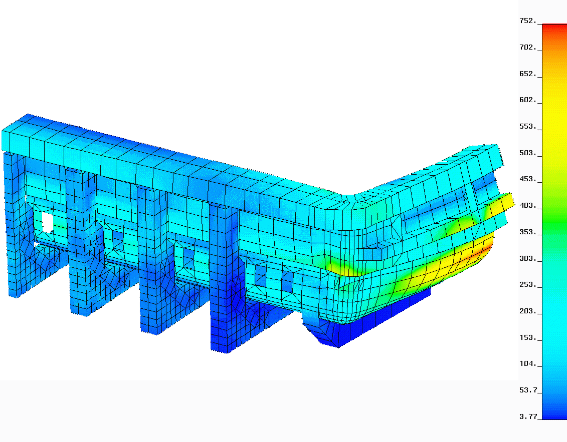
Figure 2: 65 kA Hall-Héroult Cell : Initial Design Stress Distribution
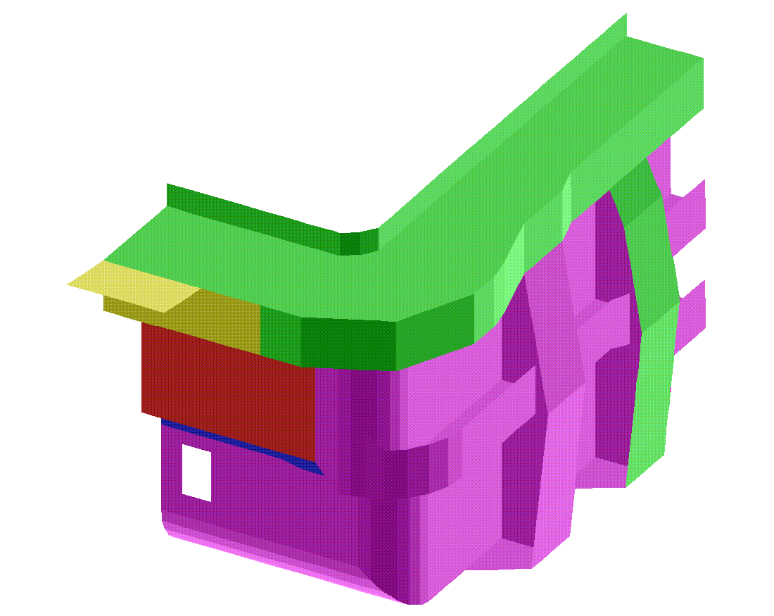
Figure 3: Modified 65 kA Hall-Héroult Cell Cathode Shell : Model Geometry
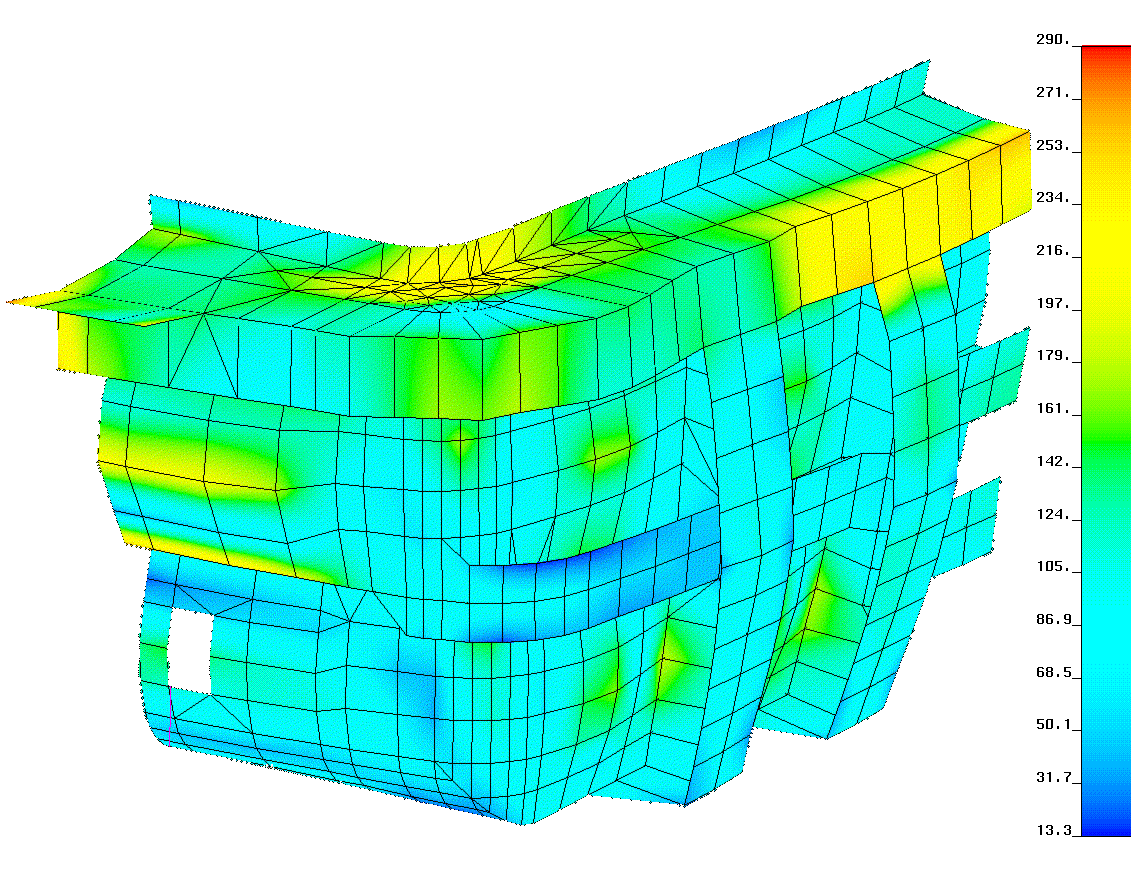
Figure 4: Modified 65 kA Hall-Héroult Cell Cathode Shell : Stress Distribution