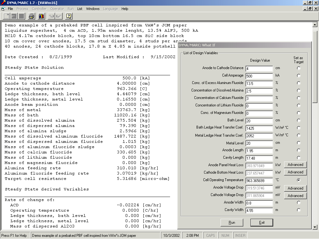
Figure 1: Dyna/Marc 1.7 "What if" panel

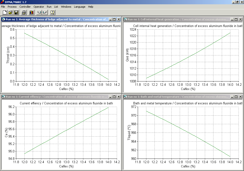
Figure 2: Dyna/Marc 1.7 Trend Analysis Results

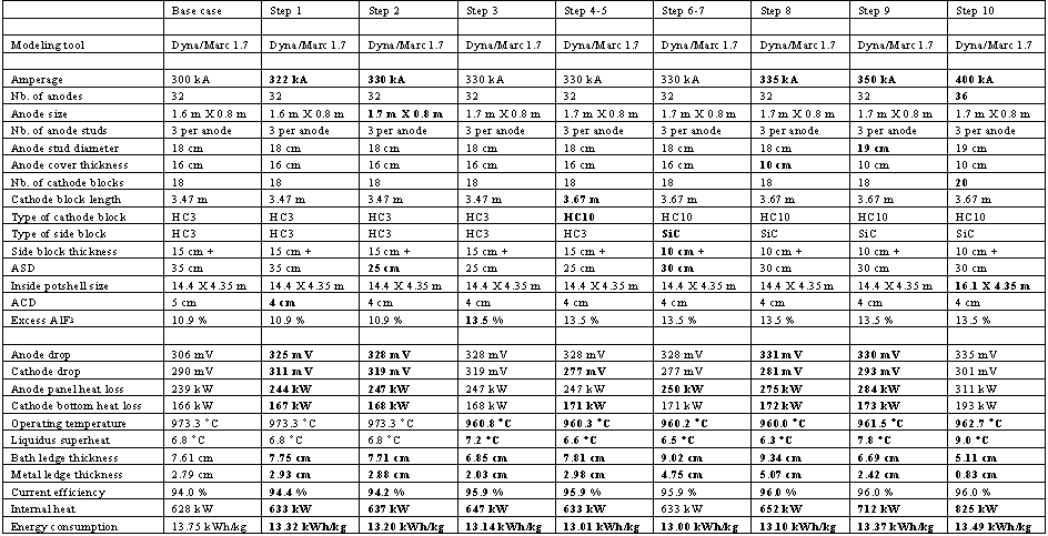
Table I : Going from 300 to 400 kA

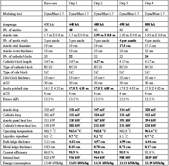
Table II : Going from 400 to 500 kA

Marc Dupuis
GéniSim Inc.
3111 Alger St.,
Jonquière, Québec, Canada G7S 2M9
email:
Introduction
It is important to well understand the physic of the heat dissipation inside the lining of an aluminum reduction cell to be able to do the thermo-electric design of a new cell.
The key feature to take into consideration is the 2 zones heat loss mechanism [1,2]. In one zone, the driving force is the global thermal gradient between the cell operating temperature and the cell ambient temperature. While in the other zone, the driving force is the cell superheat!
These days, no one would attempt to design a cell without the support of mathematical modeling tools. The simplest possible model that is representative of the two zones heat dissipation mechanism of the cell is the lump parameters+ model [3,4]. That model is so simple, that you can get answer to "what if" design questions in a fraction of second. Nevertheless, as demonstrated in [5,6], the accuracy of the lump parameters+ model predictions are surprisingly accurate considering its simplicity.
As described in [7], the lump parameters+ model has been recently upgraded by adding to it four new sub-models that computed the anode panel heat loss, the cathode bottom heat loss, the anode drop and the cathode drop. With the addition of these new sub-models, the lump parameters+ model also called Dyna/Marc 1.7 cell simulator [8] can be use stand-alone to do per example the thermo-electric design of a 500 kA cell starting from an existing design at 300 kA. Figure 1 and 2 respectively present Dyna/Marc 1.7 "What if" panel and the results of a trend analysis.
From 300 to 400 kA
The initial steps going from 300 to 400 kA have already been presented twice so far. In reference [5,7], the step-by-step retrofit study of a 300 kA cell into a 350 kA cell is first presented. In total 9 changes were required to be able to push the amperage up to 350 kA, they are:
| 1) | Decreasing the ACD from 5 to 4 cm |
| 2) | Increasing the anode length from 1.6 to 1.7 m |
| 3) | Increasing the excess AlF3 from 10.9 to 13.5 % |
| 4) | Substituting the cathode block grade from HC3 to HC10 |
| 5) | Increasing the cathode length from 3.47 to 3.67 m |
| 6) | Substituting the side block material from HC3 carbon to silicon carbide |
| 7) | Decreasing the side block thickness from 15 to 10 cm |
| 8) | Decreasing the anode cover thickness from 16 to 10 cm |
| 9) | Increasing the stud diameter from 18 to 19 cm |
The retrofitted 350 kA cell design is then extended into a 400 kA cell by increasing the cell length by 1.7 m, going from 14.4 to 16.1 m, to be able to add four new anodes and two new cathode blocks. The summary of the results obtained is presented in table I.
From 400 to 500 kA
Now for the first time, a step-by-step study of the extension of this 400 kA cell into a 500 kA cell is presented. In total four changes were required to be able to push the amperage up to 500 kA, they are:
| 1) | Increasing the cell length by 1.7 m, going from 16.1 to 17.8m, adding four new anodes and two new cathode blocks |
| 2) | Increasing the cell width by 0.5 m, going from 4.35 to 4.85 m in order to be able to increase the anode length by 0.25m going from 1.7 to 1.95 m |
| 3) | Increasing the number of studs per anode going from three 19 cm diameter studs to four 17.5 cm diameter ones |
| 4) | Increasing the number of cathode blocks from 22 to 24 by decreasing their width, effectively decreasing the current density in the collector bars. |
The summary of the results obtained is presented in table II. Obviously, this is only one possible way to get there; the MHD stability study could dictate that other choices for the length to width ratio of the cell are preferable.
Conclusions
It was demonstrated that with enough experience and a good modeling tool, it is fairly simple to do the thermo-electric design of a 500 kA cell. Apart from its quite impressive size, there is really nothing special about the design because as far as the thermo-electric aspect of the cell design is concerned, there is no specific challenges preventing the design of even bigger cell.
References
Figure 1: Dyna/Marc 1.7 "What if" panel

Figure 2: Dyna/Marc 1.7 Trend Analysis Results

Table I : Going from 300 to 400 kA

Table II : Going from 400 to 500 kA
