3D MODELING OF THE VENTILATION PATTERN IN AN
ALUMINIUM SMELTER "POTROOM" BUILDING USING CFX-4
Dr. Marc Dupuis
GéniSim Inc.
3111 rue Alger, Jonquičre, QC, G7S 2M9
|
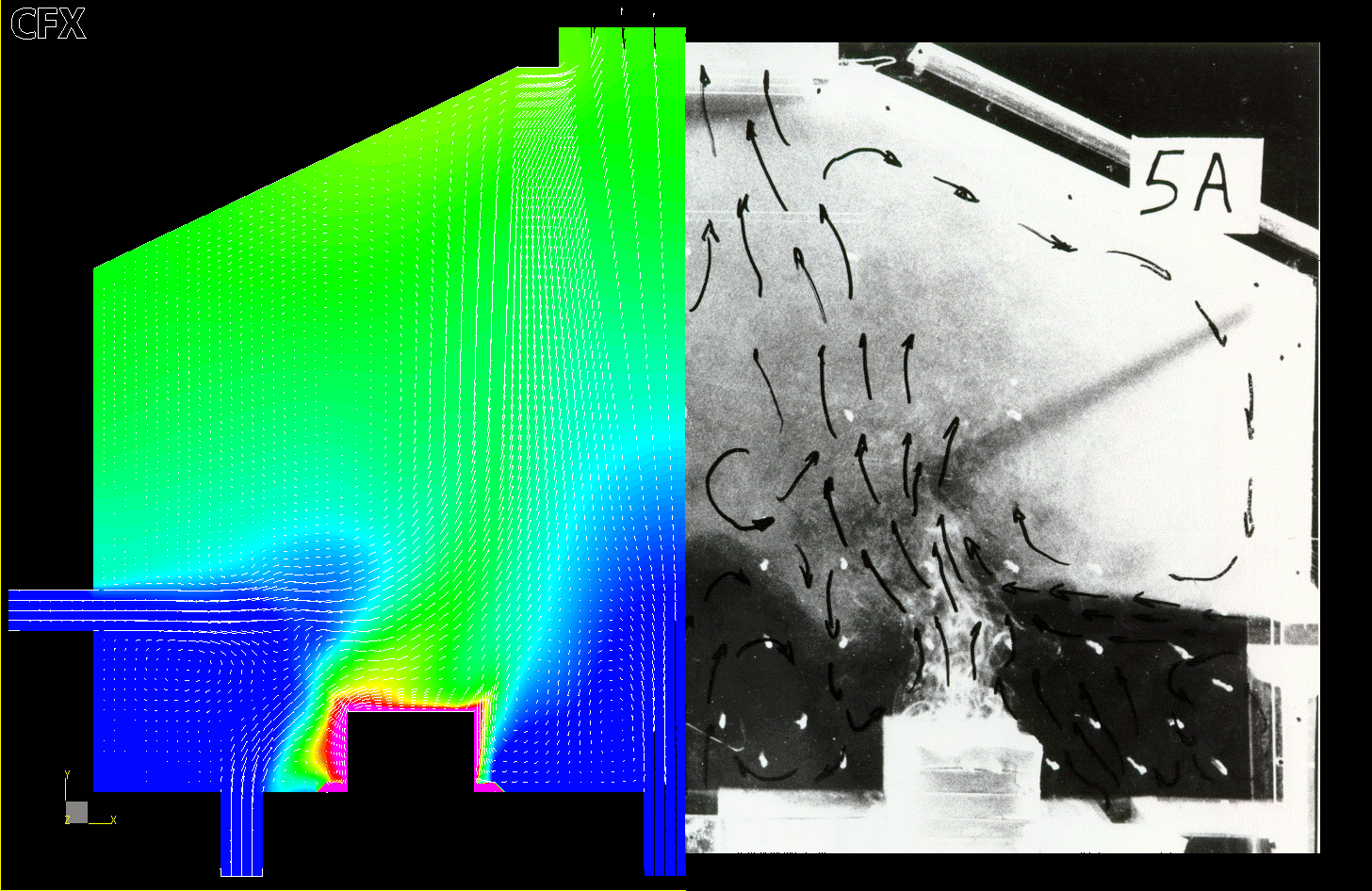
ABSTRACT The mix convection air circulation pattern inside an aluminium smelter "potroom" building is rather hard to reproduce in a mathematical model. As it was demonstrated previously [1], only the use of a differential Reynolds flux turbulence model available in the CFX-4 commercial code led to the accurate reproduction of the 2D flow pattern observed in a small physical model. As the ventilation pattern in a modern smelter "potroom" building is truly 3 dimensional in nature, the next logical step was to develop a 3D ventilation model to be able to carry out industrial applications. As before, the model was developed using the CFX-4 commercial code in order to use the differential Reynolds flux turbulence model that in 3D requires the solution of 10 partial differential equations. INTRODUCTION The proper ventilation of aluminium smelter "potroom" buildings is important for two main reasons:
For those reasons, the proper design of the building is an important aspect of a smelter technology [2]. Nowadays, one would hopes that it would |
be relatively straightforward to use CDF mathematical tools to study the ventilation pattern inside a proposed building design and utilize that tool to come up with the optimal design. Unfortunately, early works have demonstrated that it is not that easy to reproduce in a CFD mathematical model the observed turbulent mix convection flow pattern [3,4]. Yet, it was demonstrated in 1993 [1], that the observed 2D flow pattern could be well reproduced if a differential Reynolds flux turbulence model is used (see Figure 1). Such a turbulence model was available at the time in the commercial code FLOW3D from Harwell Lab. As the flow pattern in modern smelter buildings is truly tridimensional in nature [5], the present work presents the development of a 3D ventilation model of a modern potroom configuration based on the same commercial code now called CFX-4 and distributed by AEA. Obviously, that new model will also rely on the use of the differential Reynolds flux turbulence model that in 3D requires the solution of 10 partial differential equations (hh, hu, hv, hw, uu, uv, uw, vv, vw, ww).
DESCRIPTION OF A MODERN SMELTER Modern smelter buildings are more than 25 m wide, around 15 m high (excluding the basement) and can be up to 1 km long (see Figure 2). Such a building can shelter up to 100 pots aligned side by side, each being close to 14 m long and 4 m wide. Only the top part of the pots (called the superstructure) stands above the building floor. The hotter bottom part (called the potshell) is located in the building basement. |
Figure 1: Model results vs experimental flow, 2D case
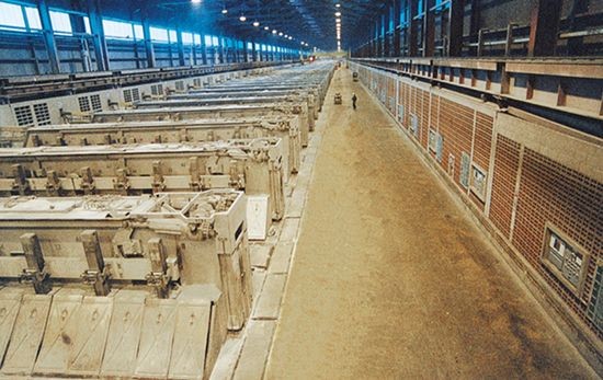
Figure 2: Modern smelter "potroom" building configuration
|
Each pot dissipates around 600 kW of heat, of which 70 to 80% has to be in turn dissipated by the building, the rest being captured by the gas scrubber system. The potroom ventilation pattern is driven by mix convection. Roof ventilators ensure the main "flow through" air circulation. All the fresh air is coming in the building by wall inlets located at the basement level. Fresh air in the basement can travel up in the potroom either by the lower section of the potroom side walls, which are porous, or by grids in the floor located around each pot. In addition to the main "flow through" air circulation, there is a secondary flow driven by natural convection above the pots. As this secondary flow cannot escape out at the roof exit, it forms a recirculating flow in the roof section of the potroom.
DESCRIPTION OF THE CFD Contrary to older technology where the pots were aligned end to end, the modern side by side arrangement generates a truly tridimensional flow pattern. This means that, in the best conditions away from the end of the building where repetitive symmetry cannot be assumed, the model depth can be reduced to the half distance between two successive pots (see Figure 3). |
For the presented mesh density, the model is made of 163,590 finite volumes. As the differential Reynolds flux turbulence model is being used, there are a total of 15 partial differential equations that needs to be solved at each node. As the model is not converging with the default setting, the temperature has to be underrelaxed to ensure smooth convergence. For that reason, the model required around 800 iterations to converge. Since each iteration requires 22 CPU seconds on a PIII 800 mHz computer, the total convergence required 4.9 CPU hours.
RESULTS OF THE CFD The model results demonstrate that the building design is very efficient to address the two main objectives since the flow pattern ensures that both the pots and the floor working area are well ventilated:
|
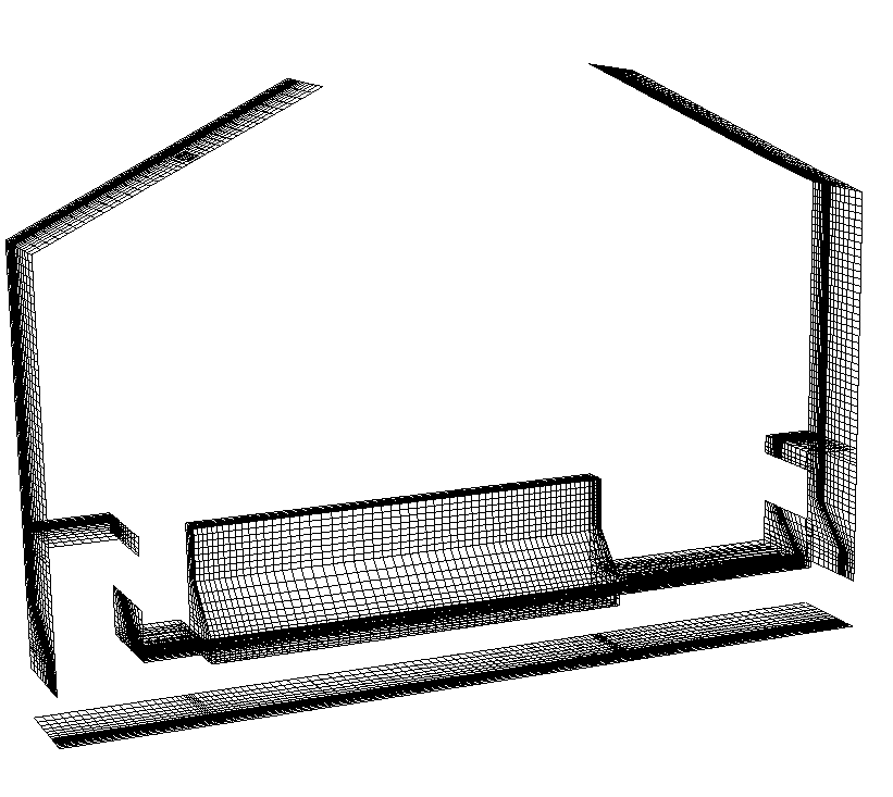
Figure 3: Model mesh at solid boundaries
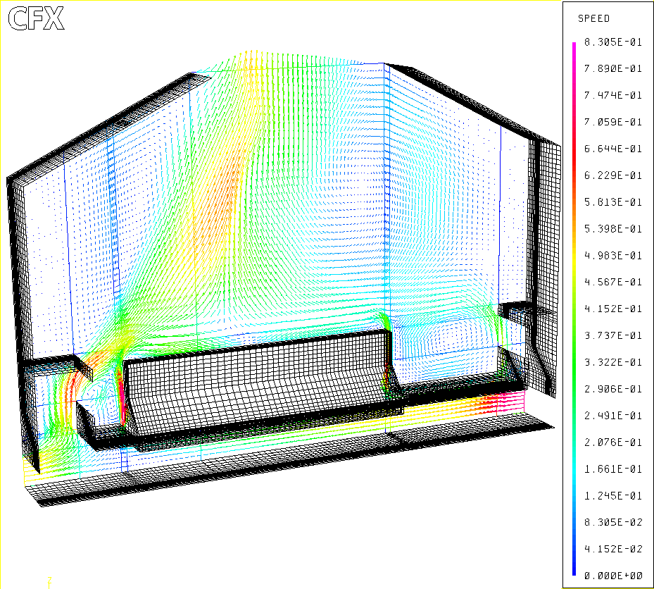
Figure 4: Velocity vector plot, back plane
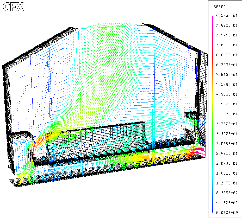
Figure 5: Velocity vector plot, front plane
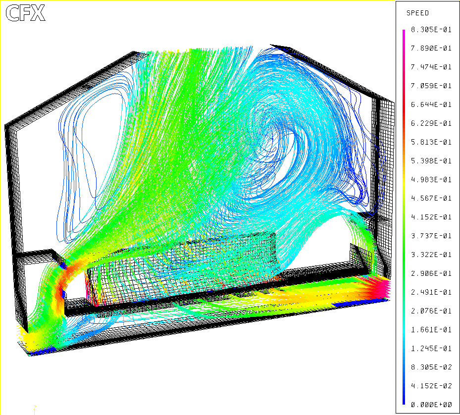
Figure 6: Streak lines
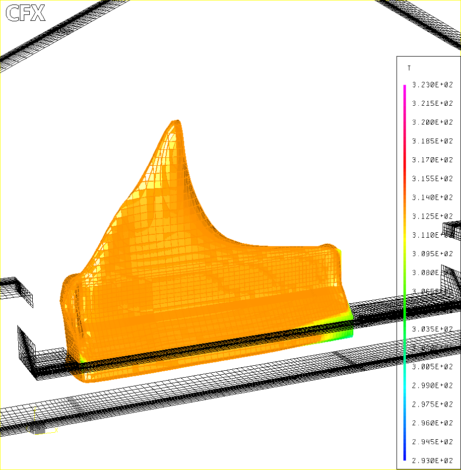
Figure 7: Isosurface at constant temperature
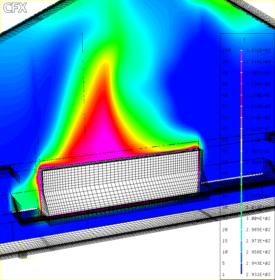
Figure 8: Fringe plot, temperature
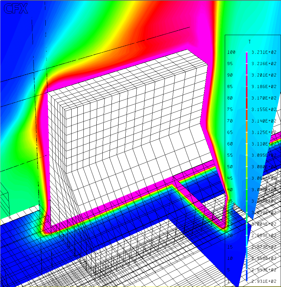
Figure 9: Fringe plot, temperature
|
CONCLUSION A full 3D ventilation model of a modern potroom design has been successfully developed using the CFX-4 code from AEA. The model relies on the differential Reynolds flux turbulence model to be able to reproduce correctly the turbulent mix convection ventilation pattern. The model is converging to the steady state conditions in around 5 CPU hours on a 800 mHz PIII computer despite the fact that 15 partial differential equations need to be solved and that the temperature has to be underrelax to ensure smooth convergence. Models results confirm the efficiency of the modern potroom design to maintain both the pots and the floor working area well ventilated. REFERENCES
|