 ER(cm/year) = A(cm/year) + B(cm/(year A/cm2)) * CD(A/cm2)
(1)
ER(cm/year) = A(cm/year) + B(cm/(year A/cm2)) * CD(A/cm2)
(1)
Development of a 3D transient thermo-electric cathode panel erosion model of an aluminum reduction cell
Marc Dupuis GéniSim 3111 Alger St., Jonquière, Québec, Canada G7S 2M9 email:
ABSTRACT
It is now rather well established that the cathode panel erosion rate is proportional to the current density. So, faster erosion in location of initial higher current density will promote further concentration of that current density as the cathode resistance is getting smaller where carbon thickness is getting thinner.
This process has been reproduced in a new type of mathematical model in order to be able to establish then compare the expected pot life of different cathode lining designs.
INTRODUCTION
For high amperage cells, graphitized carbon cathode blocks are now the preferred choice because, contrarily to the graphitic blocks, their use prevent the cathodic resistance to increase to catastrophic level with cell age (1). Unfortunately, graphitized cathode blocks are characterized by an increased erosion rate that limits, in current cell designs, the cell life to a maximum of 2500 days (1).
Furthermore, extensive measurement campaigns clearly show that the erosion rate is proportional to the cathode block surface current density (1, 2). For that reason, the most straightforward way to gain back pot life is to equalize the surface current density (3). Typically, this would be performed by studying different lining designs, using a mathematical model (3).
MODEL DESCRIPTION
For the purpose of carrying up such lining design retrofit studies, a 3D transient thermo-electric cathode panel erosion model has been developed on the commercial final element code ANSYS® . That model is the extension of the already available 3D thermo-electric cathode model (4, 5, 6).
The existing 3D thermo-electric model is already computing the steady-state cathode heat loss, ledge profile and cathode drop. Of course, the cathode blocks surface current density at the steady-state ledge toe position is part of the obtained solution.
Addition of an erosion law
The only thing missing to build a transient cathode panel erosion model that would be able to compute the cathode panel erosion evolution up to the point of failure of the cell is an erosion law:
ER(cm/year) = A(cm/year) + B(cm/(year A/cm2)) * CD(A/cm2)
(1)
Typically, constants A and B would be adjusted in order to minimize the difference between the model predictions and a measured erosion profile like the one presented in Figure 9 of reference 1.
Solution strategyStarting with the as-built geometry, the initial heat balance, ledge profile, cathode drop and surface current density are computed (standard thermo-electric solution).
Using the surface current density, the erosion law and a user-defined time step, the cathode block thickness is reduced locally generating an erosion profile in the model.
Using the eroded geometry, heat balance, ledge profile, cathode drop and surface current density are updated.
As the updated surface current density will invariably have a bigger maximum current density, the erosion law will systematically compute a higher maximum erosion rate the second time around.
Theoretically, this loop is carried out until the thickness of the carbon above the collector bar reaches zero at the location of the maximum erosion rate. In practice, at least in the current model implementation, the finite element solver starts to complain about badly deformed shape elements well before that!
Nevertheless, the analysis is carried out long enough to be able to extrapolate the evolution of the maximum erosion rate up to the theoretical point of failure.
TYPICAL BASE CASE MODEL SOLUTION
In order to present model results as close as possible to existing high amperage cells, yet using public domain informations, the base case cell design presented here is inspired from the one published in a JOM February 1994 article (7).
Based on the erosion rate reported this year in Reny et al. TMS paper (2), the parameter B of the erosion law is set to 4 cm/(year A/cm2). Parameter A is arbitrarily set to zero because there is not enough public domain informations to establish a value. Figure 17 of reference 3 could have been used to establish the value of parameter A and B, but unfortunately the current density scale is missing!
Figure 1 shows the obtained erosion profile and the corresponding surface current density after two years of erosion using 0.25 year time steps.
Figure 2 presents the evolution of the maximum erosion rate. It can be noticed that despite the current density concentration mechanism described above, the maximum erosion rate remains almost constant, in perfect agreement with the measurement reported by Reny et al.
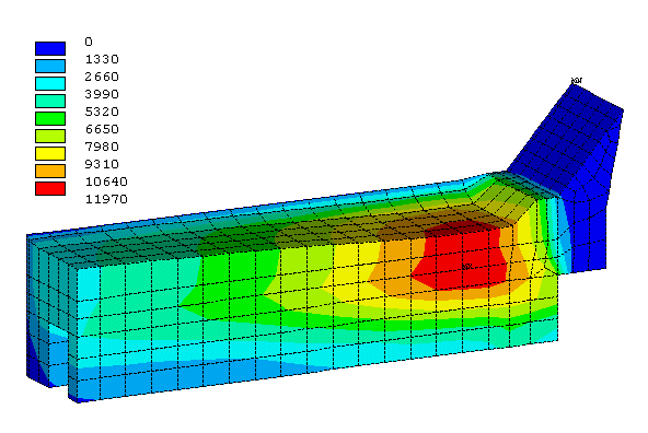
Figure 1: Erosion profile of the base case model after 2 years
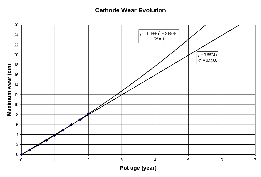
Figure 2: Evolution of the maximum erosion of the base case model
This is explained by the fact that the electrical resistance of the graphitized carbon block itself is small compared with the collector bar resistance and the cast iron/carbon contact resistance. So, even a significant erosion profile hardly affects the surface current density distribution.
Yet, even if the acceleration of the erosion rate is too small to be measured experimentally, the impact of that acceleration is big enough to remove one year of theoretical maximum cell life, if an accurate parabolic extrapolation is used instead of a linear one to compute it (2012 vs 2379 days).
ANALYSIS OF A FIRST RETROFIT PROPOSAL
Now that we have a model that well represents the erosion rate phenomenon, the next step is to modify the existing design to improve the predicted theoretical cell life by reducing the current density gradient on the cathode surface.
There is many ways to achieve this. A simple one would be to create local current pick-up points along the bar by removing some of the cast iron (see Figure 3).
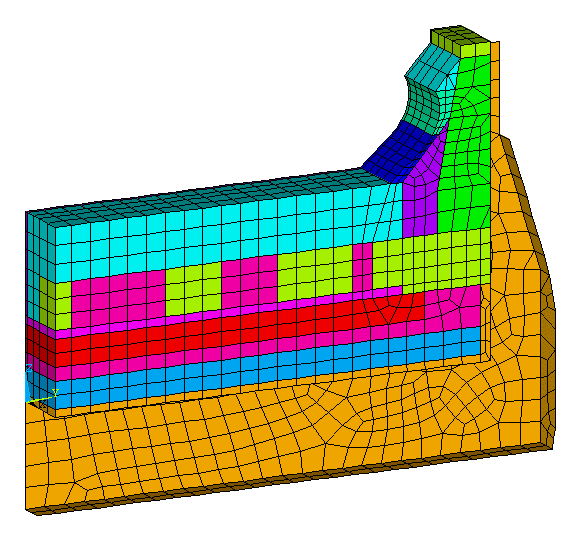
Figure 3: Geometry of the first retrofit proposal
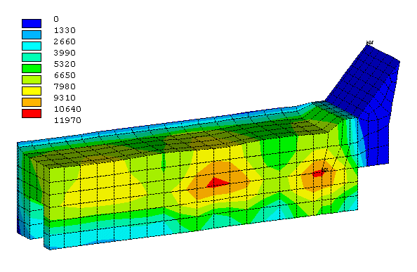
Figure 4: Erosion profile of the first retrofit proposal after 2 years
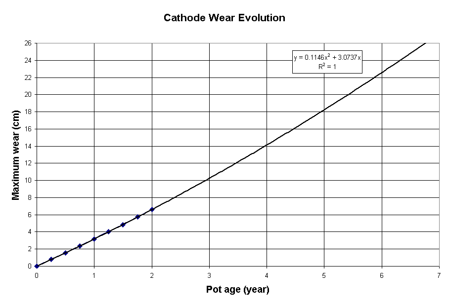
Figure 5: Evolution of the maximum erosion of the first retrofit proposal
To compensate for the natural geometry bias toward the edge of the block, the current pick-up points are bigger toward the center of the block, creating a counter effect bias this time toward the center.
As it can be seen in Figure 4, this non-optimized configuration already produces an almost uniform current density and a corresponding quite uniform erosion rate on the cathode surface. The price to pay is an increase of 23% of the cathode drop (from 273 to 335 mV) even with an increase of 20% of the collector bar width (from 10 to 12 cm).
Despite the drastic improvement of the surface current density, the predicted theoretical maximum cell life remains quite low at 2468 days (see Figure 5). This can be easily explain by the fact that even with a uniform surface current density, an erosion rate of 4 cm/(year A/cm2) still translates into a fairly high maximum erosion rate.
ANALYSIS OF A SECOND RETROFIT PROPOSAL
The above retrofit study demonstrates the limit of the surface current density equalization on the increase of the maximum theoretical cell life. Until someone discovers a way to reduce the graphitized carbon block erosion rate express in terms of cm/(year A/cm2), the height of carbon material above the bar will remain the primary limiting factor of the cell life.
Clearly, more carbon material is needed above the collector bar to expand the cell life and one could not expect to find a simple and efficient solution by looking at the block and bar/block configuration alone!
Yet, a simple solution to the graphitized cathode carbon block fast erosion rate problem exists from an opportunity created by another property of that same graphitized carbon block: its very low sodium expansion coefficient.
It is rather ironic to think that for almost a century the aluminum industry was designing pot shells too weak to maintain their integrity while exposed to the huge internal pressure resulting from the high sodium expansion coefficient of anthracite carbon blocks (8). Then, in the 70's, pot shells were finally designed strong enough to withstand that huge pressure. Nowadays, the same very strong pot shells are being used with the graphitized carbon blocks that do not have a big swelling coefficient. Clearly, those pot shells are much too strong for the new type of internal load generated by the expansion of those graphitized carbon blocks!
For this reason, this second retrofit proposal increases the cathode block height by 10 cm without decreasing the cell cavity simply by reducing by 10 cm the height of the horizontal cradles web under the pot shell floor (i.e. moving the pot shell floor down 10 cm, see Figure 6).
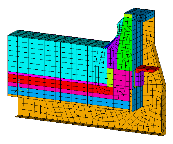
Figure 6: Geometry of the second retrofit proposal
To further compensate for the cathode drop increase generated by the use of localized cast iron current pick-up points along the bar, it is proposed to increase the collector bar height by 20% (from 20 to 24 cm). After both the increase of 10 cm of the block height and the increase of 4 cm of the bar height, an increase of 6 cm of the initial carbon height above the bar (from 26 to 32 cm) is obtained.
Figure 7 shows the obtained erosion profile after 2 years of operation. More importantly, Figure 8 presents the corresponding theoretical cell life of 3509 days. Furthermore, with its cross-section increase of 44% compared to the base case design, the cathode drop is only raised by 7% (from 273 to 293 mV).
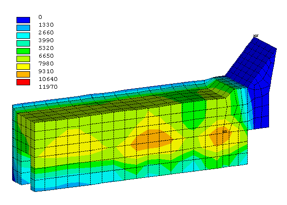
Figure 7: Erosion profile of the second retrofit proposal after 2 years
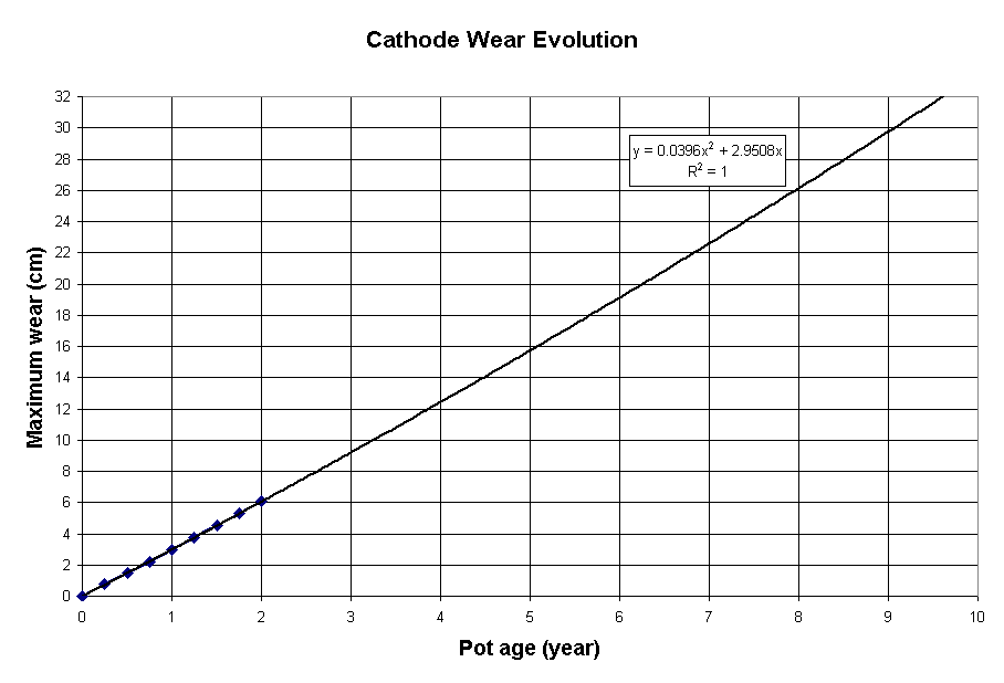
Figure 8: Evolution of the maximum erosion of the second retrofit proposal
CONCLUSIONS
A new 3D transient thermo-electric cathode panel erosion model has been successfully developed and tested. This new tool can be used to predict theoretical cell life of any retrofit design proposal aiming at decreasing maximum erosion rate and improving cell life.
In the spirit of the last TMS conference where the participants were invited to think out of the box, an innovative yet simple retrofit design proposal was demonstrated to be an effective way to almost double the theoretical maximum cell life of an high amperage cell using graphitized cathode blocks.
REFERENCES