 |
 |
ABSTRACT
An aluminum reduction cell is very complex to model as it involves different multi-physics processes like thermo-electric, thermo-mechanic, thermo-electro-mechanic, magneto-hydro-dynamic, etc.
The author will review its 18 years experience in that field and will discuss about the future challenges that still remain to be addressed.
INTRODUCTION
Finite element modeling is now a maturing technology. This means that major breakthroughs in codes capabilities are getting sparser. Obvious, easy-to-implement applications have already been developed and are now routinely being used.
Yet, for more complex, typically multi-physics applications, the finite element technology remains a marginally used design tool even nowadays. One example the author is intimately familiar with is the application of ANSYS based models to support the development and retrofit of aluminum reduction cell.
Aluminum reduction cells are very complex to model because it is a truly multi-physics modeling application involving, to be rigorous, a fusion of thermo-electro-mechanic and magneto-hydro-dynamic modeling capabilities in a complex 3D geometry. Even after around 20 years of steady development, the ultimate fully coupled multi-physics finite element model of an aluminum reduction cell remains a dream tool and will remain so for many years to come.
To try to predict when, if even, such an advanced modeling tool could be finally developed, lets gain some perspective by reviewing the personal implication of the author in the field of ANSYS based aluminum reduction cell model development.
1984, 3D thermo-electric half anode model:
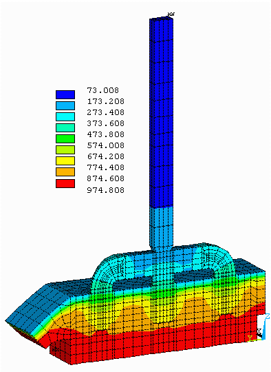
The personal involvement of the author started early in the aluminum industry conversion phase where it shifted from developing in-house finite difference models toward developing finite element models based on commercial codes like ANSYS (Reference 1). In 1984, he was assigned to the development of a 3D thermo-electric half anode ANSYS model (References 1, 2 and 3, see figure 1). That model was developed on ANSYS 4.1 installed on a shaded VAX 780 platform. That VAX was running a wide variety of applications as it was the only general purpose computer used by an R&D organization of around 500 peoples. A Tektronix 4107 terminal was used to work on the VAX via a long distance dedicated telephone line as that VAX was physically located in another city.
It took 6 months to build that model, including the time spent to learn ANSYS and the aluminum reduction cell technology. An instrumented anode campaign similar to the one presented in (Reference 3) was also organized and carried out during the same period to support the model validation phase. That very first 3D half anode model of around 4000 Solid 69 thermo-electric elements took 2 weeks elapse time to compute on the VAX in the background batch "NEVER QUEUE".
The development and successful validation of that model was considered as a major achievement at the time, but the model potential application in an anode retrofit study was not considered practical then. Later on, several anode prototypes were successfully designed with that type of half anode model.
1986, 3D thermo-electric cathode side slice and cathode corner model:
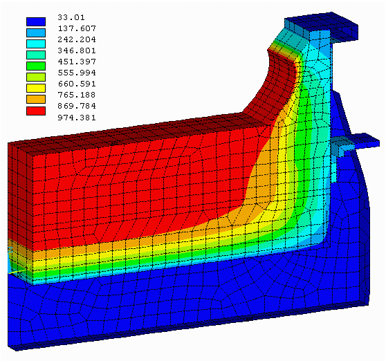
The next step was the development of a 3D cathode side slice thermo-electric model that included the calculation of the thickness of the solid electrolyte phase on the cell side wall (References 1, 2 and 3, see figure 2). This involved the addition of an extra convergence loop on the geometry of the model in order to satisfy both the temperature and the heat flux boundaries conditions on the solidified surface.
This loop was programmed in a .COM file in the VAX VMS environment. In that loop, ANSYS was called as a subroutine. The calculation of the new nodes position was computed in an external FORTRAN program also called as a subroutine in the .COM file. The mesh had obviously to be very crude as the extra geometry convergence loop added around an order of magnitude to the CPU time required by ANSYS to solve a fix geometry thermo-electric problem. In this first side ledge thickness convergence loop implementation, the solution from the previous loop was not use as initial guess to solve the next loop.
Despite the very serious limitations on the size of the mesh, a full cathode corner (Reference 3) was built next, more to demonstrate the capability to do so than to actually use the model as a design tool as the model turn around time was not at all convenient!
 |
 |
Figure 1: 3D thermo-electric half anode model Figure 2: 3D thermo-electric cathode side slice model
1989, 3D cathode potshell plastic deformation mechanical model:
After the migration of the computer platform from a VAX VMS environment to a SGI UNIX environment and the recoding of the cathode ledge thickness convergence loop directly in ANSYS using APDL and the successful application of the above models to design some cell prototypes, it was decided to expand the modeling capability into a new direction.
The new model type addresses a different aspect of the physic of an aluminum reduction cell, namely the mechanical deformation of the cathode steel potshell under its thermal load and more importantly its internal pressure load. The internal pressure buildup is coming from the gradual swelling of the cell lining as it absorbs sodium during the cell operation.
The requirements for that type of model were quite different from those of the thermo-electric models. The full quarter of the shell structure had to be meshed and that mesh had to be fine enough to be able to accurately compute the level of stress in the potshell structure. Obviously, 2D shell plastic mechanical elements were used, initially only the triangular shape was available! Providing an accurate thermal loading on the potshell structure was a difficulty as no quarter thermo-electric models were available.
Finally, running in plastic mode was quite a challenge for 3 reasons:
| 1) | Even on the brand new P-IRIS 4D/20, the CPU time required to solve such a model was excessive, the initial debugging runs had to be done on a Convex C1 computer running in England. |
| 2) | The ANSYS non-linear solver was not very robust at the time. |
| 3) | Since potshell designs were very weak, most of them were actually failing under their maximum load in real life (Reference 4, see figure 3). |
Yet, over the years, this type of model turned out to be quite an asset, as most if not all of the potshell were eventually redesigned in order to prevent excessive plastic deformation. This drastically reduced potshell repair costs and contributed to increase cell life.
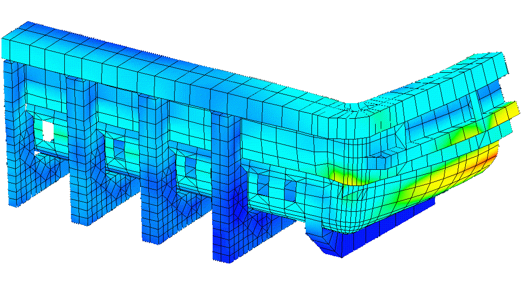
Figure 3: 3D cathode potshell plastic deformation mechanical model
1992, 3D thermo-electric quarter cathode model:
With the upgrade of the P-IRIS to 4D/35 processor, and the option to run on a CRAY XMP supercomputer, the severe limitations on the CPU usage were finally partially lifted. This opened the door to the possibility to develop a full 3D thermo-electric quarter cathode model including the ledge thickness convergence loop (References 5, 6 and 7, see figure 4).
Obviously again, the fact that you could build and solve that type of model on an experimental basis did not mean that you could plan to use that tool on a routine basis as en efficient design tool !
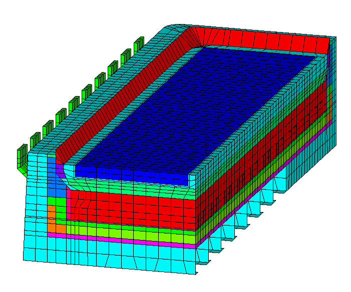
Figure 4: 3D thermo-electric quarter cathode model
1992, 3D thermo-electric full cell and external busbars model:
This time frame corresponds to an intense phase of experimental model development. As a first step toward the development of a first thermo-electro-magnetic model, a 3D thermo-electric full cell and external busbars model was developed (References 6 and 8, see figure 5). That model was really at the limit of what could be built and solved on the available hardware at the time both in terms of RAM memory and disk space storage.
To reduce the size of the model, only the purely thermo-electric elements of the quarter cathode model were mirror twice. Of course, the converged ledge geometry from the quarter cathode model was used and kept fixed. Finally, the temperature solution from the quarter cathode model was also forced as boundaries conditions on those cathode elements.
So only the external busbars were truly solved as fully coupled thermo-electric elements. Obviously, the electric solution in the cell reflected the imperfect balance of the external busbars so the electric solution was different from the forced symmetric solution obtained with the quarter cathode model. In turn of course, this change in the electric solution should have affected the temperature solution and the converged ledge thickness. Yet, that coupling had to be neglected as the fully coupled problem could not be possibly fit in the available computer.
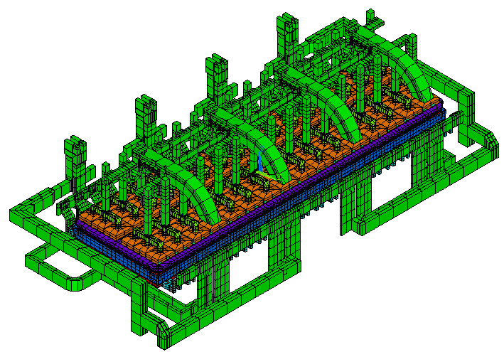
Figure 5: 3D thermo-electric full cell and external busbars model
1992, 3D cathode potshell plastic deformation and lining swelling mechanical model:
On the other front of model development, the empty quarter potshell mechanical model was extended to take into account the coupled mechanical response of the swelling lining and the restraining potshell structure. As the carbon lining swelling due to sodium intercalation is somewhat similar to material creeping, different models that represented that behavior were developed (References 6 and 9, see figure 6). However, notice that the most interesting and CPU demanding model has never been published.
That coupling was important to consider as a stiffer, more restraining potshell would face more internal pressure from the swelling lining material. Obviously, that additional load needed to be considered in order to truly design a potshell structure that will not suffer extensive plastic deformation.
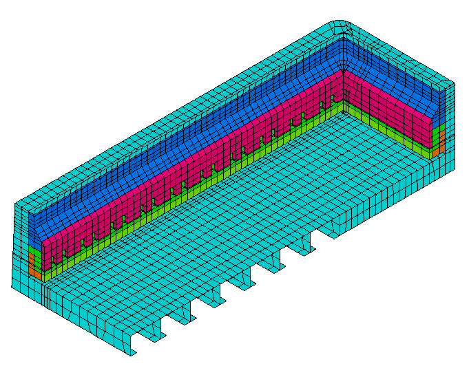
Figure 6: 3D cathode potshell plastic deformation
1993, 3D electro-magnetic full cell model:
The development of a finite element based aluminum reduction cell magnetic model clearly represented a third front of model development. The ability to solve the magnetic field inside an aluminum reduction cell is a key requirement in order to be able to design a stable high amperage cell (i.e. a cell that does not amplify small bath-metal interface perturbation into long MHD driven traveling wave).
For a finite element solver, it is not a straightforward application as the requirements are multiple, the model must be able to:
| 1) | deal with locally distributed current sources; |
| 2) | deal with far field current sources; |
| 3) | deal with a multiply connected ferro-magnetic thin wall structure (the potshell) that is shielding the inside of the cell from the far field current sources. |
Because of the presence of the ferro-magnetic shielding structure, the solution of the magnetic problem cannot be reduced to a simple Biot-Savard integration scheme. Instead, solving the problem using the finite element method requires meshing the empty space around the cell up to the point where semi-infinite special boundaries elements can be used. Obviously, the model solution is non-linear because of the non-linear magnetic properties of the ferro-magnetic shielding structure.
Starting with version 5.0A, ANSYS could be used to solve that problem. Obviously, because the full cell and its surrounding empty space had to be meshed, this type of model required a tremendous amount of computing resources. An experimental version of that type of model was developed and run on a CRAY C90 supercomputer (Reference 8, see figure 7).
That model required so much computer resources, that the next planned development phase, the extension of the full cell thermo-electric model presented above into a full cell thermo-electro-magnetic model was cancelled. To this day, the aluminum industry still relies on in-house developed boundaries element codes to compute the cell magnetic field (Reference 10), often using a very approximate representation of the ledge geometry leading to a magnetic field calculation based on very approximate locally distributed current sources (Reference 7).
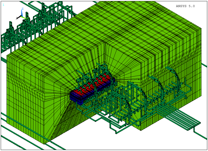
Figure 7: 3D electro-magnetic full cell model
1993, 3D transient thermo-electric full quarter cell preheat model:
Driven by an urgent plant request, the cathode quarter thermo-electric model was extended into a full quarter cell geometry in preheat configuration and ran in transient mode in order to analyze the cell preheat process (References 11, 12 and 13, see figure 8). The need was urgent, but again due to its huge computing resources requirements, the model was not ready in time to be used to solve the plant problem at the time.
Fortunately, since then, the model results were finally put to contribution to solve the plant problem when it resurfaced. So again, we have here an example of delayed model success story.

Figure 8: 3D transient thermo-electric full quarter cell preheat model
1998, 3D thermo-electric full cell slice model:
In 1994, the aluminum industry was in the middle of a smelting overcapacity crisis and reacted among other things by a wave of R&D budgets cut. Cutting the funding for the development of expensive and "unproductive" aluminum reduction cell models seemed the right thing to do in that context.
So at that time, the author stopped working for the R&D organization of a major aluminum company and started working as a consultant. After a few years of consolidation, he was able to finance his own R&D activities in the field of aluminum reduction cell model development. The 3D thermo-electric full cell slice model is the first new model developed that way.
As described previously, the 3D half anode model and the 3D cathode side slice model have been developed in sequence, and each separately required a fair amount of computer resources. Merging them together was clearly not an option at the time, yet it would have been a natural thing to do. Many years later, the hardware limitation no longer existed so they were finally merged (Reference 1, see figure 9).
1998, 2D+ thermo-electric full cell slice model:
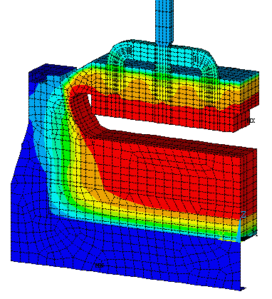
At the same time, a 2D+ version of the same full cell slice model was developed. Solving a truly three dimensional cell slice geometry using a 2D model may sound like a step in the wrong direction, but depending on the objective of the simulation, sometimes it is not so. Having both models available is in that context an advantage.
The 2D+ model uses beam elements to represent geometric features lying in the third dimension (the + in the 2D+ model). Even that way, some geometric representation accuracy is of course lost compared to a true 3D model, but on the other hand, the payback is almost an order of magnitude gain on the model usage turn around time (Reference 1, see figure 10). That type of speedup becomes very important in the context of the utilization of that kind of model in transient mode.
 |
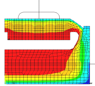 |
Figure 9: 3D thermo-electric full cell slice model Figure 10: 2D+ thermo-electric full cell slice model
1999, 2D+ transient thermo-electric full cell slice model:
|
So not much later, a transient version of the 2D+ full cell slice model was developed. An interesting feature of that model is the extensive APDL coding that computes other aspects of the process related to the different mass balances like the alumina dissolution, the metal production and the cell controller actions like the alumina feeding and the anode cathode adjustment (References 14 and 15, see figure 11). As that type of model has to compute the dynamic evolution of the ledge thickness, there is a lot more involved than simply activating the ANSYS transient mode option. Unfortunately, as each transient load step has to alternate with a geometry change and an initial condition initialization load step, the current numerical scheme is far from being efficient. Clearly, there is a need for further development on that type of model. |
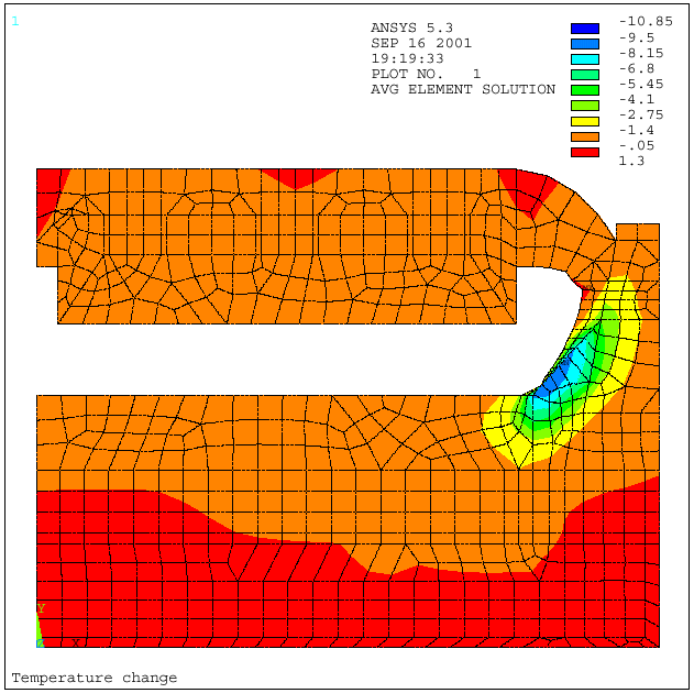 |
Figure 11: 2D+ transient thermo-electric full cell slice model
2000, 3D thermo-electric full quarter cell model:
The continuous increase of the computer power now allows not only to merge the anode to the cathode in a cell slice model but also in a full quarter cell model (Reference 16, see figure 12). The liquid zone can even be included if the computation of the current density in that zone is required for MHD analysis (Reference 7).
We are not yet at the point where we can plan to solve a full cell and external busbars thermo-electric model on a US $2000 PC, but this time will come soon!
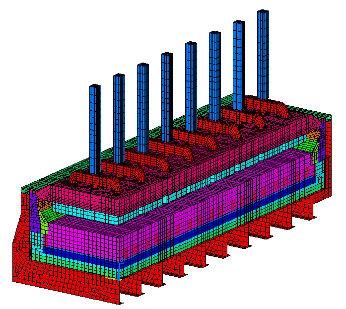
Figure 12: 3D thermo-electric full quarter cell model
2000, 3D thermo-electric cathode slice erosion model:
As the needs of the industry evolve, new types of models are required. In the past, cathode swelling was a big problem. Now, with the new types of cathode block, it is the cathode fast erosion rate that creates a problem.
As this erosion rate is proportional to the cathode surface current density and that the initial surface current density is not uniform, the erosion profile will not be uniform. Furthermore, that initial erosion profile will promote further local concentration of the surface current density that in turn will promote a further intensification of the non-uniformity of the erosion rate.
That extra physics can be incorporated in a standard thermo-electric cathode model. In turn, that new type of model can be used to investigate potential design improvements that are dealing with the erosion problem (Reference 17, see figure 13).
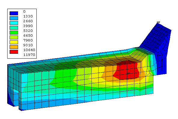
Figure 13: 3D thermo-electric cathode slice erosion model
2000, 3D thermo-electro-mechanic half anode model:
In the anode manufacturing process, cast iron is pour between the steel stud and the carbon block to joint the two pieces. As the contact between the cast iron and the carbon remains imperfect, a significant voltage drop occurs at that interface while the anode is in operation.
In the standard thermo-electric half anode model, that extra contact resistance is added to the model as an extra radial electrical resistivity in the cast iron. So it is up to the model user to adjust the intensity of the extra cast iron radial electrical resistivity in order for the model to accurately reproduce the measured contact drop during model calibration (Reference 3).
Yet, that contact resistance per unit surface depends on the stud hole design, as it is inversely proportional to the average contact pressure between the cast iron and the carbon. The average contact pressure itself depends on the steel stud diameter, the average cast iron thickness, the details interface geometry and the relative thermal expansion of the 3 materials involved. Finally, the relative thermal expansion itself depends on the different materials operating temperature that in turn depends on the contact resistance as it is responsible of an extra very localized production of Joule heat.
The anode stud/cathode block cast iron connection system thus is a perfect example of fully coupled thermo-electro-mechanic behavior. This complex behavior was successfully reproduced in a model by Daniel Richard in his master study project. That model was then successfully used to improve the stud hole design in order to minimize the voltage drop due to contact resistance (References 18 and 19).
As for past developments, the author believes that the rate of future model development will be mainly dictated by the Moore law. As stated at the beginning, the ultimate goal as far as model development is concerned is the development of a fully coupled multi-physics model of a full electrolysis cell. Why? Simply because in an electrolysis cell many different interrelated types of physics are involved and all of those interactions have a significant impact on the process:
| 1) | The potshell must be mechanically designed so that it will not plastically deform under its thermal and lining expansion pressure loading. Yet, that loading depends on the lining design, itself mostly dictated by the thermo-electric behavior of the cell; |
| 2) | The potshell could also be designed for its ferro-magnetic shielding impact on the magnetic field, itself affecting the cell MHD stability; |
| 3) | The potshell temperature and mechanical deformation change its ferro-magnetic shielding characteristics; |
| 4) | The potshell deformation and the cathode blocks heaving/erosion affect the geometry of the cell cavity which itself affects the local thickness of the metal pad; |
| 5) | The local variation of the metal pad thickness directly affects the local horizontal current density which itself affects the cell MHD stability; |
| 6) | The shape of the cell cavity and the local variation of the metal pad thickness also affect the local cathode blocks surface temperature and the potential for local sludge accumulation on the cathode surface; |
| 7) | The local cathode block surface temperature and local sludge accumulation affect the potential of forming hard alumina deposition on the cathode surface, itself affecting the local current density, in turn affecting the MHD metal flow and MHD cell stability; |
| 8) | The cell thermo-electric design affects the ledge thickness which itself affects the horizontal current density, in turn affecting the cell MHD stability; |
| 9) | The cell MHD stability affects the anode-cathode adjustment which itself affects the cell heat balance, in turn affecting the ledge thickness. |
Only a fully coupled thermo-electro-mechanico-magneto-hydro-dynamic model could be used as a design tool in order to fully take into accounts all of those complex interactions. On the other hand, such a model even if it could be available today, could not be used as a practical design tool as it would require far too much computer resources to have a manageable turn around time. That is why the Moore law will continue to be an important factor in future models development rate.
Step 1, 3D thermo-electric full cell and external busbars model:
As stated previously, expending a full quarter cell model into a full cell and external bus model is no big deal, all there is to do is simply to mirror twice the full quarter cell and add a few thousands elements for the external busbars. Such a model could be solved on a P4 1.6 GHz with 2 GB of RAM and 2 40 GB hard drives today. Such a PC may cost more than US $2000 right now, but even at twice that price that remains quite affordable even for a process engineer working in a smelter.
Step 2, 3D thermo-electro-magnetic full cell and external busbars model:
The next step would be to remesh the potshell with 3D elements and mesh the air around the cell and busbars in order to be able to solve the magnetic field. For that preprocessing step, it would be nice if ANSYS could provide an automatic way to generate that air mesh. As example, the surface on the existing mesh could be used to create a single volume and a single "air" volume could be generated by subtracting that single "cell" volume from a bigger volume incorporating it.
Once the air mesh is available, there is no harm trying to solve the magnetic field using the solution of the previous model as current source and the potshell temperature to define its ferro-magnetic property using the above computer. If the problem could be solved on that computer in an acceptable turn around time, it would represent a major step forward accomplished very rapidly. If not, we will simply have to wait for the next generation computer !
Step 3, 3D electro-magneto-hydro-dynamic full cell and external busbars model:
The next step may require coupling of ANSYS with a powerful CFD solver for solving the cell MHD flow, which is very demanding. The CFD code must be able to solve an immiscible two liquid phases MHD driven flow, which includes the solution of the position of an internal free interface between the two liquids. In addition, the top liquid phase flow is also driven by the drag of bubble release in addition to the MHD Lorentz body force.
Solving the above flow problem with a constant Lorentz body force field is already quite a challenge and should already require a lot of computing resources. Unfortunately, that would be neglecting an important coupling effect. As the bath-metal interface deforms, the shape of the anodes must be readjusted to keep the anode cathode distance constant. This change of geometry will for sure affects the bubble release pattern.
Rigorously, the change of the bath-metal interface and of the anodes shape also affected the current density field in the metal pad, which in turn affected the magnetic field so both need to be updated. Then the CFD problem needs to be solved again with the new anode shape and the updated MHD Lorentz body force. Hopefully after a few iterations between the CFD solution and the anode geometry and MHD Lorentz body force update, the global solution will nicely converge!
Clearly, there are a lot of challenges associated with the successful development of this step:
| 1) | The CFD code must be able to converge efficiently this closed domain, multi-phases, body force driven problem; |
| 2) | If required, the interfacing of ANSYS with the CFD solver must be smooth and efficient (in 1993, the author successfully coupled ANSYS and FIDAP in order to solve a MHD flow in a simple test problem); |
| 3) | Updating the magnetic field must be performed at a minimum computing cost (Biot-Savard subtraction of old source terms and addition of the new ones, then restarting of the non-linear convergence from the previous solution); |
| 4) | Restarting the CFD convergence after an update of the anode geometry and MHD Lorentz force must be equally efficient. |
Finally, even with the most efficient numerical scheme, solving this problem will require tremendous computing resources. Solving this type of problem may not become affordable before 2 or even 3 computer generations from now!
Step 4, 3D thermo-electro-magneto-hydro-dynamic full cell and external busbars model:
After having solve a fully coupled electro-magneto-hydro-dynamic model using a fixed ledge geometry, it is time to consider yet another coupling: the impact of the flow solution on the liquid/ledge heat transfer coefficient and hence on the shape of the ledge thickness.
Practically, this means that after having solved the initial flow solution, the local heat transfer coefficient on the liquid/ledge interface must be reevaluated and the thermo-electric ledge convergence loop must be repeated in addition to the anode geometry adjustment. The rest of the numerical scheme remains the same of course, the current density will be updated as part of the thermo-electric ledge convergence process so the magnetic field needs to be updated. Yet this time in addition to the Biot-Savard source term changes, the ferro-magnetic shielding property of the potshell needs to be updated as well as the potshell temperature changed as part of the thermo-electric ledge convergence process.
Implementing step 4 on top of step 3 is quite straightforward, yet obviously the required computer resources are getting even bigger with each additional interaction added to the numerical scheme.
Step 5, 3D thermo-electro-mechanical-magneto-hydro-dynamic full cell and external busbars model:
Now that we have a converged ledge profile compatible with the MHD flow on an assumed rigid potshell geometry, we can solve the "simple" cathode potshell plastic deformation and lining swelling mechanical model to obtain the deformed shape of the potshell and the corresponding deformed shape of the cell cavity.
This may sound like a minor issue, but on a 15 meters long potshell, the maximum vertical deflection can reach 5 cm. As the metal pad is around 20 cm thick, we are talking about a 25% variation, which will have a significant impact on the heat loss distribution, the local ledge thickness, the local metal current density, etc. As this is definitively not a weak coupling, the addition of that extra interaction effect on the numerical scheme of step 4 will further increase the required computer resources one more time.
Step 6, 3D thermo-electro-mechanical-magneto-hydro-dynamic full cell and external busbars model coupled with a 3D slice potroom ventilation model:
As the potshell deformation is added to the list of multi-physics coupled interactions, it becomes important to point out that the potshell temperature is also strongly influenced by the potroom ventilation pattern. This type of coupling between the potshell heat loss and the potroom ventilation has already been modeled by Ingo Eick (Reference 20). He combined ANSYS and FIDAP to build his model.
Coupling step 5 model with a potroom slice ventilation model like the one presented in Reference 21 could become quite important as potshell length continue to increase (References 22 and 23).
Step 7, adding the dispersed alumina phase to the CFD model:
As stated previously, the settling of the dispersed alumina on the cathode blocks surface affects the current distribution and the heat loss partition. Adding the solid dispersed alumina phase and the physics of alumina dissolution and sedimentation in the CFD model could become important in order to get a model 100% representative of the reality as everything else has already being considered.
The physics of the alumina dissolution/sedimentation in the cell could already be the key limiting factor in drain cathode and inert anode/drain cathode R&D projects. In those innovative designs, the metal pad is removed and the anode cathode distance is greatly reduced. In those designs, the alumina dissolution and the sludge formation become an even more critical aspect of the process (Reference 24).
CONCLUSIONS
Considering the model developments that still remain to be done, it may well be possible that even after 20 years of continuous development, we are only half way through it and there are still as many years of further model developments ahead of us. Not that that much time is required to actually do those developments but simply because we need that many computer generations before a complete multi-physics aluminum reduction cell model could become an affordable and efficient design tool for the industry.
For sure, the aluminum industry is not currently in a rush to develop that modeling technology, even if the current aluminum reduction cell technology developments (References 22, 23 and 24) could certainly greatly benefit from it. In addition to having to wait for the Moore law to continue to take effect, the industry will probably need increased environmental pressure to produce aluminum with less energy and with less greenhouse gas emission before it feels the need to modernized its smelting capacity (Reference 25). The bottom line being that high tech computer models will become strategic assets only after the aluminum industry massively shifts from operating old less efficient cell technologies towards operating more efficient but also much more complex and challenging high amperage cell technologies.
REFERENCES